“Virtual image, a point or system of points, on one side of a mirror or lens, which, if it existed, would emit the system of rays which actually exists on the other side of the mirror or lens.”
One way to describe an image using numbers is to declare its contents using position and size of geometric forms and shapes like lines, curves, rectangles and circles; such images are called vector images.
We need a coordinate system to describe an image, the coordinate system used to place elements in relation to each other is called user space, since this is the coordinates the user uses to define elements and position them in relation to each other.
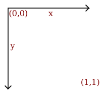
The coordinate system used for all examples in this document has the origin in the upper left, with the x axis extending to the right and y axis extending downwards.
It would have been nice to make a smiling face, instead of the dissatisfied face on the left, by using a bezier curve, or the segment of a circle this could be achieved, this being a text focusing mainly on raster graphics though, that would probably be too complex.
A simple image of a face can be declared as follows:
Figure 1.2. Vector image
draw circle
     center        0.5, 0.5
     radius        0.4
     fill-color    yellow
     stroke-color  black
     stroke-width  0.05
draw circle
     center        0.35, 0.4
     radius        0.05
     fill-color    black
draw circle
     center        0.65, 0.4
     radius        0.05
     fill-color    black
draw line
     start         0.3, 0.6
     end           0.7, 0.6
     stroke-color  black
     stroke-width  0.1

The preceding description of an image can be seen as a “cooking recipe” for how to draw the image, it contains geometrical primitives like lines, curves and cirles describing color as well as relative size, position and shape of elements. When preparing the image for display is has to be translated into a bitmap image, this process is called rasterization.
A vector image is resolution independent, this means that you can enlarge or shrink the image without affecting the output quality. Vector images are the preferred way to represent Fonts, Logos and many illustrations.
Bitmap-, or raster [1] -, images are “digital photographs”, they are the most common form to represent natural images and other forms of graphics that are rich in detail. Bitmap images is how graphics is stored in the video memory of a computer. The term bitmap refers to how a given pattern of bits in a pixel maps to a specific color.
![[Note]](images/note.png) | Note |
|---|---|
In the other chapters of introduction to image molding, raster images is the only topic. |
Figure 1.3. Raster image
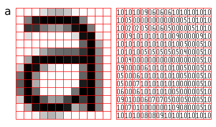
A bitmap images take the form of an array, where the value of each element, called a pixel picture element, correspond to the color of that portion of the image. Each horizontal line in the image is called a scan line.
The letter 'a' might be represented in a 12x14 matrix as depicted in Figure 3., the values in the matrix depict the brightness of the pixels (picture elements). Larger values correspond to brighter areas whilst lower values are darker.
When measuring the value for a pixel, one takes the average color of an area around the location of the pixel. A simplistic model is sampling a square, this is called a box filter, a more physically accurate measurement is to calculate a weighted Gaussian average (giving the value exactly at the pixel coordinates a high weight, and lower weight to the area around it). When perceiving a bitmap image the human eye should blend the pixel values together, recreating an illusion of the continuous image it represents.
The number of horizontal and vertical samples in the pixel grid is called Raster dimensions, it is specified as width x height.
Resolution is a measurement of sampling density, resolution of bitmap images give a relationship between pixel dimensions and physical dimensions. The most often used measurement is ppi, pixels per inch [2].
Figure 1.4. Sampling grid
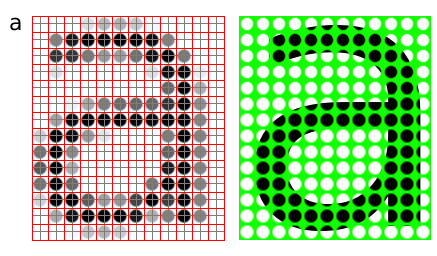
Megapixels refer to the total number of pixels in the captured image, an easier metric is raster dimensions which represent the number of horizontal and vertical samples in the sampling grid. An image with a 4:3 aspect ratio with dimension 2048x1536 pixels, contain a total of 2048x1535=3,145,728 pixels; approximately 3 million, thus it is a 3 megapixel image.
Table 1.1. Common/encountered raster dimensions
| Dimensions | Megapixels | Name | Comment |
|---|---|---|---|
| 640x480 | 0.3 | VGA | VGA |
| 720x576 | 0.4 | CCIR 601 DV PAL | Dimensions used for PAL DV, and PAL DVDs |
| 768x576 | 0.4 | CCIR 601 PAL full | PAL with square sampling grid ratio |
| 800x600 | 0.4 | SVGA | |
| 1024x768 | 0.8 | XGA | The currently (2004) most common computer screen dimensions. |
| 1280x960 | 1.2 | ||
| 1600x1200 | 2.1 | UXGA | |
| 1920x1080 | 2.1 | 1080i HDTV | interlaced, high resolution digital TV format. |
| 2048x1536 | 3.1 | 2K | Typically used for digital effects in feature films. |
| 3008x1960 | 5.3 | ||
| 3088x2056 | 6.3 | ||
| 4064x2704 | 11.1 |
When we need to create an image with different dimensions from what we have we scale the image. A different name for scaling is resampling, when resampling algorithms try to reconstruct the original continous image and create a new sample grid.
The process of reducing the raster dimensions is called decimation, this can be done by averaging the values of source pixels contributing to each output pixel.
When we increase the image size we actually want to create sample points between the original sample points in the original raster, this is done by interpolation the values in the sample grid, effectivly guessing the values of the unknown pixels[3].
The values of the pixels need to be stored in the computers memory, this means that in the end the data ultimately need to end up in a binary representation, the spatial continuity of the image is approximated by the spacing of the samples in the sample grid. The values we can represent for each pixel is determined by the sample format chosen.
Figure 1.5. Sample depth
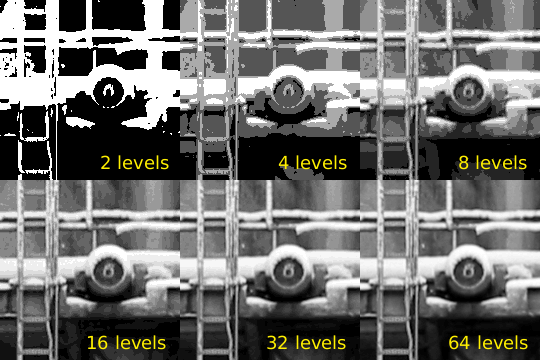
A common sample format is 8bit integers, 8bit integers can only represent 256 discrete values (2^8 = 256), thus brightness levels are quantized into these levels.
For high dynamic range images (images with detail both in shadows and highlights) 8bits 256 discrete values does not provide enough precision to store an accurate image. Some digital cameras operate with more than 8bit samples internally, higher end cameras (mostly SLRs) also provide RAW images that often are 12bit (2^12bit = 4096).
The PNG and TIF image formats supports 16bit samples, many image processing and manipulation programs perform their operations in 16bit when working on 8bit images to avoid quality loss in processing.
Some image formats used in research and by the movie industry store floating point values. Both "normal" 32bit floating point values and a special format called half which uses 16bits/sample. Floating point is useful as a working format because quantization and computational errors are kept to a minimum until the final render.
Floating point representations often include HDR, High Dynamic Range. High Dynamic Range images are images that include sampling values that are whiter than white (higher values than 255 for a normal 8bit image). HDR allows representing the light in a scene with a greater degree of precision than LDR, Low Dynamic Range images.
The most common way to model color in Computer Graphics is the RGB color model, this corresponds to the way both CRT monitors and LCD screens/projectors reproduce color. Each pixel is represented by three values, the amount of red, green and blue. Thus an RGB color image will use three times as much memory as a gray-scle image of the same pixel dimensions.
Figure 1.6. RGB bands
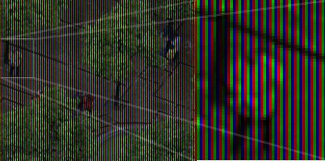
One of the most common pixel formats used is 8bit rgb where the red, green and blue values are stored interleaved in memory. This memory layout is often referred to as chunky, storing the components in seperate buffers is called planar, and is not as common.
It was earlier common to store images in a palletized mode, this works similar to a paint by numbers strategy. We store just the number of the palette entry used for each pixel. And for each palette entry we store the amount of red, green and blue light.
Figure 1.7. Indexed image
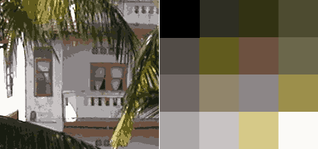
Bitmap images take up a lot of memory, image compression reduces the amount of memory needed to store an image. For instance a 2.1 megapixel, 8bit RGB image (1600x1200) occupies 1600x1200x3 bytes = 5760000 bytes = 5.5 megabytes, this is the uncompressed size of the image.
Compression ratio is the ratio between the compressed image and the uncompressed image, if the example image mentioned above was stored as a 512kb jpeg file the compression ratio would be 0.5mb : 5.5mb = 1:11.
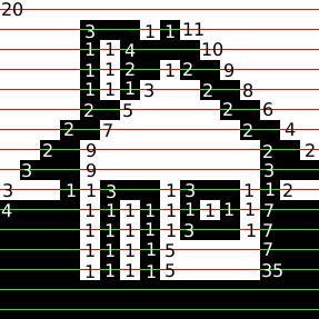
When an image is losslessly compressed, repetition and predictability is used to represent all the information using less memory. The original image can be restored. One of the simplest lossless image compression methods is run-length encoding. Run-length encoding encodes consecutive similar values as one token in a data stream.
Figure 1.8. Run-length encoding
70,
5, 25,
5, 27,
4, 26,
4, 25,
6, 24,
6, 23,
3, 2, 3, 22,
3, 2, 3, 21,
3, 5, 2, 20,
3, 5, 2, 19,
3, 7, 2, 18,
3, 7, 2, 17,
14, 16,
14, 15,
3, 11, 2, 14,
3, 11, 2, 13,
3, 13, 2, 12,
3, 13, 2, 11,
3, 15, 2, 10,
3, 15, 2, 8,
6, 12, 6, 6,
6, 12, 6, 64
In Figure 1.8, “Run-length encoding” a black and white image of a house has been compressed with run length encoding, the bitmap is considered as one long string of black/or white pixels, the encoding is how many bytes of the same color occur after each other. We'll further reduce the amount of bytes taken up by these 72 numerical values by having a maximum span length of 15, and encoding longer spans by using multiple spans separated by zero length spans of the other color.
70,                     15,  0, 15,  0, 15,  0, 10,
 5, 25,                  5, 15,  0, 10,
 5, 27,                  6, 15,  0, 12,
 4, 26,                  4, 15,  0, 11,
 4, 25,                  4, 15,  0, 10,
 6, 24,                  6, 15,  0,  9,
 6, 23,                  6, 15,  0,  8,
 3,  2, 3, 22,           3,  2,  3, 15,  0,  7,
 3,  2, 3, 21,           3,  2,  3, 15,  0,  6,
 3,  5, 2, 20,           3,  5,  2, 15,  0,  5,
 3,  5, 2, 19,           3,  5,  2, 15,  0,  4,
 3,  7, 2, 18,           3,  7,  2, 15,  0,  3,
 3,  7, 2, 17,           3,  7,  2, 15,  0,  2
14, 16,                 14, 15,  0,  1
14, 15,                 14, 15,
 3, 11, 2, 14,           3, 11,  2, 14,
 3, 11, 2, 13,           3, 11,  2, 13,
 3, 13, 2, 12,           3, 13,  2, 12,
 3, 13, 2, 11,           3, 13,  2, 11,
 3, 15, 2, 10,           3, 15,  2, 10,
 3, 15, 2,  8,           3, 15,  2,  8,
 6, 12, 6,  6,           6, 12,  6,  6,
 6, 12, 6, 64            6, 12,  6, 15, 0, 15, 0, 15, 0, 15, 0, 4
The new encoding is 113 nibbles long, a nibble i 4bit and can represent the value 0--4, thus we need 57 bytes to store all our values, which is less than the 93 bytes we would have needed to store the image as a 1bit image, and much less than the 750 bytes needed if we used a byte for each pixel. Run length encoding algorithms used in file formats would probably use additional means to compress the RLE stream achieved here.
Lossy image compression takes advantage of the human eyes ability to hide imperfection and the fact that some types of information are more important than others. Changes in luminance are for instance seen as more significant by a human observer than change in hue.
JPEG is a file format implementing compression based on the Discrete Cosine Transform DCT, together with lossless algorithms this provides good compression ratios. The way JPEG works is best suited for images with continuous tonal ranges like photographs, logos, scanned text and other images with lot's of sharp contours / lines will get more compression artifacts than photographs.
Lossy compression algorithms should not be used as a working format, only final copies should be saved as jpeg since loss accumulates over generations.
Figure 1.9. JPEG generation loss
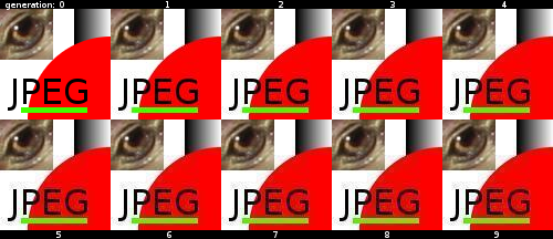
An image specially constructed to show the deficiencies in the JPEG compression algorithm, saved, reopened and saved again 9 times.
JPEG is most suited for photographics content where the adverse effect of the compression algorithm is not so evident.
JPEG is not suited as an intermediate format, only use JPEG for final distribution where filesize actually matters.
Many applications have their own internal file format, while other formats are more suited for interchange of data. Table ref# lists some common image formats.
Table 1.2. Vector File Formats
| Extension | Name | Notes |
|---|---|---|
| .ai | Adobe Illustrator Document | Native format of Adobe Illustrator (based on .eps) |
| .eps | Encapsulated Postscript | Industry standard for including vector graphics in print |
| .ps | PostScript | Vector based printing language, used by many Laser printers, used as electronic paper for scientific purposes. |
| Portable Document Format | Modernized version of ps, adopted by the general public as 'electronic print version' | |
| .svg | Scalable Vector Graphics | XML based W3C standard, incorporating animation, gaining adoption. |
| .swf | Shockwave Flash | Binary vector format, with animation and sound, supported by most major web browsers. |
Table 1.3. Raster File Formats
| Extension | Name | Notes |
|---|---|---|
| .jpg | Joint Photographic Experts Group | Lossy compression format well suited for photographic images |
| .png | Portable Network Graphics | Lossless compression image, supporting 16bit sample depth, and Alpha channel |
| .gif | Graphics Interchange Format | 8bit indexed bitmap format, is superceded by PNG on all accounts but animation |
| .exr | EXR | HDR, High Dynamic Range format, used by movie industry.. |
| .raw, .raw | Raw image file | Direct memory dump from a digital camera, contains the direct imprint from the imaging sensor without processing with whitepoint and gamma corrections. Different cameras use different extensions, many of them derivatives of TIFF, examples are .nef, .raf and .crw |
| .dgn | Digital Negative | A subset/clarification of TIFF, created by Adobe to provide a standard for storing RAW files, as well as exchanging RAW image data between applications. |
| .tiff, .tif | Tagged Image File Format | |
| .psd | Photoshop Document | Native format of Adobe Photoshop, allows layers and other structural elements |
| .xcf | Gimp Project File | GIMP's native image format. |
[1] raster n: formation consisting of the set of horizontal lines that is used to form an image on a CRT
[2] The difference between ppi and dpi, is the difference between pixels and dots - pixels can represent multiple values, whilst a dot is a monochrome spot of ink or toner of a single colorant as produced by a printer. Printers use a process called half toning to create a monochrome pattern the simulates a range of intensity levels.
[3] When using the digital zoom of a camera, the camera is using interpolating to guess the values that are not present in the image. Capturing an image at the maximum analog zoom level, and doing the post processing of cropping and rescaling on the computer will give equal or better results.
